
Define the immunity method and coupling arrangement first
Record the test method, applicable procedure, frequency span, modulation, dwell time and coupling arrangement before selecting an RF amplifier. Conducted and radiated immunity arrangements use different signal paths and can require different power budgets. Confirm the edition and conditions of the procedure used by your laboratory rather than assuming a generic amplifier is sufficient. Identify every element between the signal generator and the coupling point, including cables, directional couplers, attenuators, coupling networks or antennas, as applicable to the test arrangement.
Calculate the required power at the actual operating point
Begin with the required level at the defined test point and account for losses in the complete path. In a simple matched path, required amplifier output in dBm equals the target power in dBm plus path loss in dB. As a calculation example, a target of 20 dBm after a 6 dB loss needs at least 26 dBm at the amplifier output before additional margin is considered. This arithmetic example is not a measured HPORTEK result and does not define an immunity test level. Frequency-dependent loss, coupling factors, mismatch and the actual test procedure must also be considered.
Compare linear power and compression figures, not only model wattage
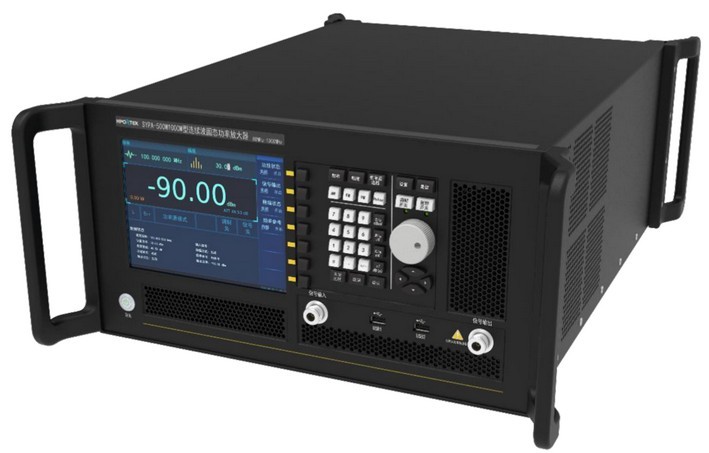
Nominal power, P1dB and P3dB describe different operating points. Determine which limit matters for the modulation and accuracy of your test. The published SYPA-500W1000M table lists at least 500 W output power, at least 475 W P3dB and at least 425 W P1dB over 80 MHz to 1000 MHz. These figures should not be treated as interchangeable. Confirm the measurement conditions, permitted duty cycle and required operating margin with engineering. Avoid using a saturated-power figure as evidence of the same output capability in a linear test.
Check band coverage across the complete sweep
The HPORTEK catalogue lists different spans for the amplifier family: 10 kHz to 1000 MHz for SYPA-10W1000M, 10 kHz to 100 MHz for SYPA-150W100M, 10 kHz to 250 MHz for SYPA-500W250M, and 80 MHz to 1000 MHz for SYPA-500W1000M. Check the actual lower and upper limits against the intended sweep. One high-power model may not cover the complete low-frequency portion of a test. If several amplifiers are needed, plan switching, calibration and level verification at the changeover points.
Review drive level, cooling, protection and monitoring
The published family tables specify a maximum RF input of 1.0 mW. Confirm the allowed input for the selected model and avoid overdriving the amplifier while trying to compensate for path loss. Provide the ventilation and installation clearance required by the equipment instructions. Input-overload, VSWR and over-temperature protection are listed for this family, but protection features do not remove the need for correct load matching and operating conditions. Include forward and reflected power monitoring where required by the procedure, and agree how a protection event or interrupted sweep will be handled.
Send a reproducible test requirement for selection
Provide the engineering team with the test method, frequency span, target level, modulation, coupling arrangement, estimated path loss, expected mismatch, duty cycle and available power supply. Ask for configuration-specific operating limits and the supported control interface. The catalogue lists local and remote control options for the amplifier family; verify the exact interface and software requirements for your system. A useful acceptance plan checks performance at representative frequencies with the intended load and measurement arrangement, records settings, and defines the evidence needed before the amplifier enters routine use.
Related products
- SYPA-10W1000M · CW Solid-State Power Amplifier
- SYPA-150W100M · CW Solid-State Power Amplifier
- SYPA-500W250M · CW Solid-State Power Amplifier
- SYPA-500W1000M · CW Solid-State Power Amplifier
Engineering guidance for initial selection. Model-specific limits and configurations must be confirmed with HPORTEK. Calculation examples are illustrative and do not represent measured product results.
Download application note (PDF · English) ↓
Back to company updates