High-Speed Acquisition & Processing Boards
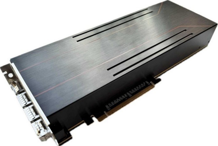
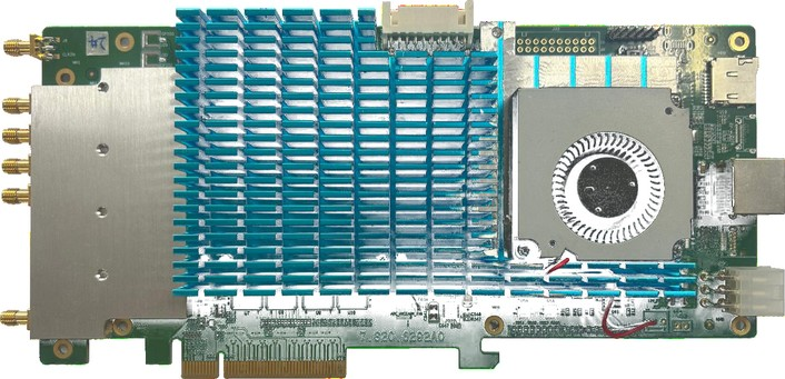
SYHS-RFSOC-PCIEHigh-Speed Acquisition & Replay Card
The SYHS-RFSOC-PCIE is an RFSOC-based PCIe high-speed signal generation and acquisition board with 4 TX and 1 RX RF…
View product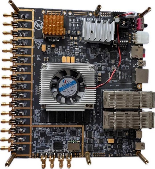
High-Speed Acquisition & Processing Boards
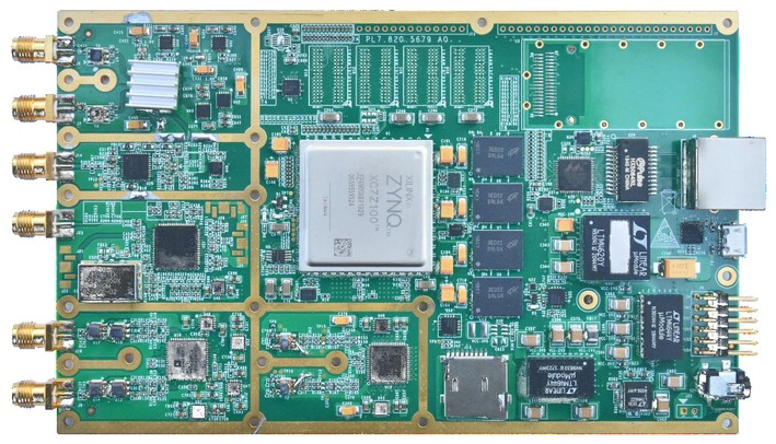
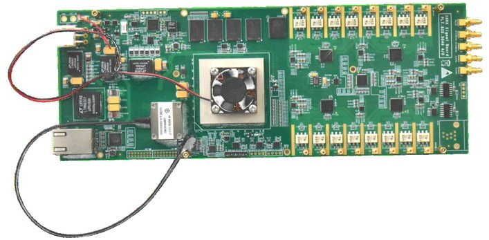
The SYHS-8R8T-2G is a wideband RF transceiver board based on the ZU47DR RFSoC, with 8 RX and 8 TX channels and up to 2 GHz instantaneous bandwidth per channel. It integrates high-speed RF-ADC/RF-DAC, UltraScale+ FPGA logic, and ARM processing for wideband acquisition, real-time arbitrary waveform generation, and on-chip DSP. The board uses optical interfaces for high-speed, low-latency bidirectional data transfer, supporting external reference clock and trigger synchronization with multi-board cascade capability.
TECHNICAL DATA
Specifications correspond to the product catalogue. Contact our technical team for configuration and operating conditions.
| Parameter | Specification / typical value |
|---|---|
| ADC | |
| Number of Channels | 8 channels |
| ADC Sampling Rate | 5Gsps(MAX.) |
| ADC Resolution | 14bit |
| ADC Effective Resolution | 10bit |
| Input Power | ≤1dBm (typical) |
| SFDR | ≥60dBc |
| Typical Instantaneous Bandwidth | 2GHz |
| Channel Phase Consistency | ≤5° |
| DAC | |
| Number of Channels | 8 channels |
| DAC Sampling Rate | 9.85Gsps(MAX.) |
| DAC Resolution | 14bit |
| Output Power | ≤5dBm |
| Typical Instantaneous Bandwidth | 2GHz |
| FPGA & Memory | |
| Logic Resources | 930K |
| CLB LUTs | 425K |
| DSP Slices | 4272 |
| Interfaces | QSFP x2; SFP x1; Ethernet x1; USB3.0 x1; GPIO 28 (LVTTL) |
| PSDDR | 4GB |
| PLLDDR | 2GB |
| General | |
| Power Supply | DC 12V@3A |
Specifications are subject to change without notice. Contact our technical team for full conditions, interface definitions, and ordering information.
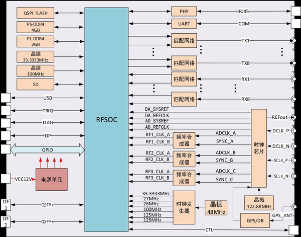
SYSTEM ARCHITECTURE
EXPLORE MORE
The SYHS-RFSOC-PCIE is an RFSOC-based PCIe high-speed signal generation and acquisition board with 4 TX and 1 RX RF…
View productThe SYHS-VU13P-PROC is a high-performance FPGA-based baseband real-time processing board. It features abundant GTY transceivers and multiple high- speed…
View productThe SYHS-DRFM is a general-purpose high-speed acquisition and generation platform integrating one dual-channel high-speed DAC, one dual-channel low- speed…
View productThe SYHS-16CH-S is a 16-channel synchronous IF acquisition card supporting DDC, digital filtering, and optical fiber data transmission.
View productLET’S CONNECT
Talk to our team about your measurement, signal processing, and system integration requirements.